Blender is a versatile open source 3D creation suite that is able to render maps with realistic lighting and textures. This article is a brief introduction to using Blender to visualize GIS data for those with some GIS and raster manipulation experience. By the end of this article you will understand how to:
- Modify GIS data so it is suitable for Blender
- Create a 3D surface from elevation data in Blender
- Drape a map over the 3D surface
- Render a 3D map with realistic lighting
The two images used to create the maps below can be downloaded Here.


Manipulate GIS Data
A 3D map can be created in Blender using two images: A map of the area of interest and a digital elevation model (DEM) that covers the area. Blender can use rasterized elevation data in a similar way to GIS software such as ArcGIS and QGIS. The software will generate a 3D surface by extruding parts of the image using DEM pixel values as the magnitude of extrusion. Then the map image is draped over top of the 3D surface and rendered with realistic lighting. DEM images can be downloaded from many sources on the internet such as government open data portals. Both the map and DEM used in this tutorial are freely available from the Government of Alberta. High resolution DEMs can also be generated from LiDAR point clouds or similar data.
Keys to Success
Avoid excessively large image files
Ensure the DEM and map are the same size and resolution
Stretch DEM pixel values
There are many ways to achieve the necessary results, but the end product must be two images with exactly the same size, resolution, and spatial extent. Where the map is extruded in Blender will depend on where there are elevation values in the DEM. Therefore flat areas will have DEM values of 0.
First, georeference the map to align it with the elevation data. Next resample either the DEM or the map so that their resolution and pixel alignment match. In ArcMap this can be achieved by using the resample tool and defining a snap raster in the environment settings.

The Final step is to fill the no data cells in the DEM within the extent of the map and stretch the elevation values. Below is a sample expression that will achieve these results using the raster calculator tool in ArcMap. It spreads the elevation values across 16 bit values and replaces null values with 0. It also maintains a minimum elevation value of 5000 so that the lowest elevations will appear to be elevated above the map in blender. Before executing the tool, set the processing extent in the environment settings to the extent of the map. Finally, create PNG copies of the two images for use in Blender.
ArcMap raster calculator expression
Int( Con( IsNull( “DEM” ), 0, ( ( “DEM” – min) / ( max – min ) * ( 65535 – 5000 ) + 5000 ) ) )
Let’s unpack that expression. The innermost part (“DEM” – min) / ( max – min ) * ( 65535 – 5000 ) + 5000 scales the pixels from 65535 to 5000 using the min and max values of DEM. Next the Con function conditionally assigns pixel values. The condition in this case is IsNull(“DEM”), so where DEM has null values (the flat areas on the “map” where there is no elevation data) a value of 0 is assigned, else the scaled pixel value is assigned. Finally, the values are converted to integers.
Create a 3D Surface in Blender Using a DEM
I suggest watching a few videos on how to navigate blender before moving on to the next steps. If you haven’t installed Blender yet, it can be downloaded Here. In the following steps, the displacement method will be used to create the 3D model for the map. The following steps in this tutorial follow the YouTube tutorial by Owen Powell. He has published a few more Blender tutorials that I strongly recommend watching too.
Step 1 Import the DEM
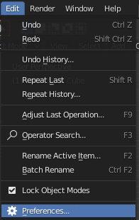
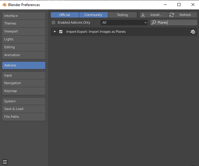
The elevation data needs to be imported as a plane. To do this, the “Import-Export: Import Images as Planes” add-on must be activated in the Blender preferences. Before importing the image, delete all other objects in the scene by pressing the “a” key then “delete”.

Step 2 Add a Light Source (Optional)
Add a light source to the scene to make everything a little brighter. The lighting will be adjusted later to enhance the relief of the map.

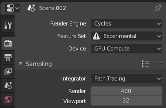
Step 3 Change Render Settings and Modifiers

Before displacing the DEM, the render settings must be changed. In the Render Properties tab change the render engine to Cycles and switch to the Experimental Feature Set.
Next, select the DEM and navigate to the Modifiers tab. From the Add Modifier drop down, select the subdivision surface modifier. Adjust the modifier parameters so they match the image below. Select the Adaptive setting and switch to the simple subdivision algorithm.


Step 4 Shaders and Textures
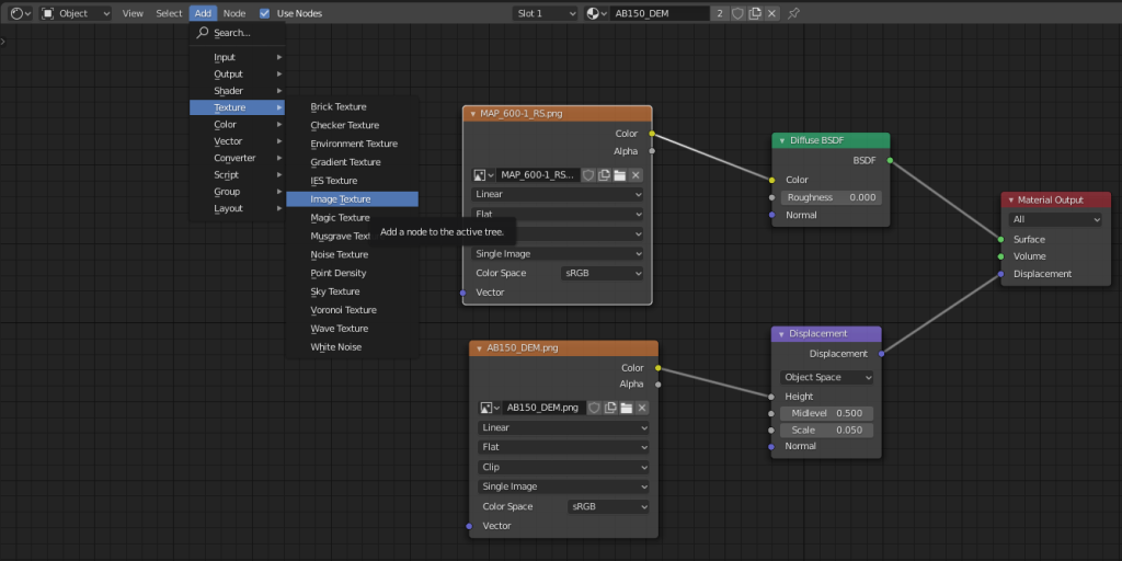
Select the DEM by clicking on it then navigate to the shader editor and add the Diffuse BSDF and Displacement nodes shown below. Connect the Color output of the image node to the Color input of the Diffuse BSDF and the Height input of the Displacement node. Connect the output of the Diffuse BSDF to the surface input of the Material Output node. Connect the displacement output of the Displacement node to the displacement input of the Material Output node. The resulting image should show some relief, but no true displacement yet.


In the materials tab of the DEM under settings, change the displacement setting from Bump Only to Displacement Only. The model should now have highly exaggerated topography like in the image below. To adjust the vertical exaggeration, change the scale setting in the Displacement node.


Drape the Map Over the Model and Add Lighting
Step 1 Add the Map as an Image Texture
In the shader editor add the map image as an image texture and replace the Diffuse BSDF Color input with the color output of the image texture node shown below. Don’t worry if the model looks like it is low resolution. Blender is displaying a simplified version to help the system manipulate the model on-the-fly. The model will be rendered in full detail later.

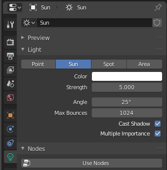
Step 2 Adjust the Lighting
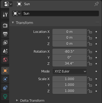
Select the sun light added earlier and change it so the light source comes from the top left of the image as a low angle. This will help create relief when the model is rendered. Experiment with multiple light sources, angles, and colors to create interesting shadows.

Render

Rendering can be processing intensive, so it is best to reduce the rendering quality until the final images are produced. Reduce the render sampling and resolution scale settings before rendering. Reducing these settings will results in a lower quality image, but can drastically reduce rendering time and still create an image that will represent how the final product will look.
Step 1 Position the Camera
Add a camera to the scene and adjust its location so that it is directly above the map. You may view the map through the camera by pressing 0 on the number pad. Adjust the camera position so that the whole map is in view. It is also best practice to change the camera to an orthographic perspective to eliminate radial displacement.


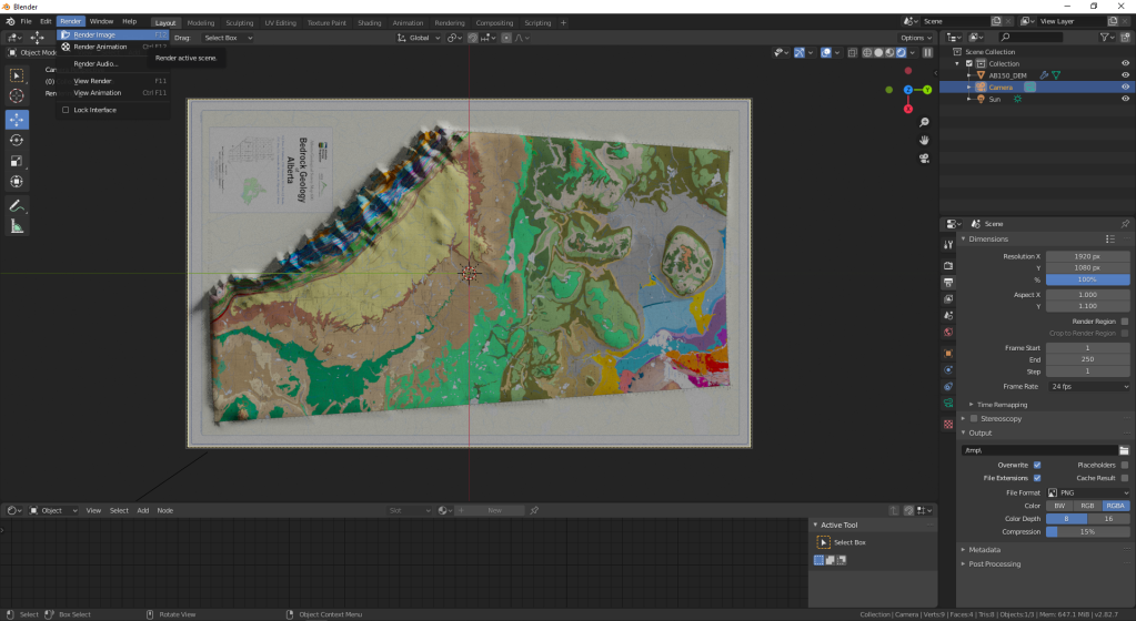
Step 2 Render the Image
Once the camera position is set, navigate to Render, Render Image at the top left corner of the window, or press F12 to render the image.
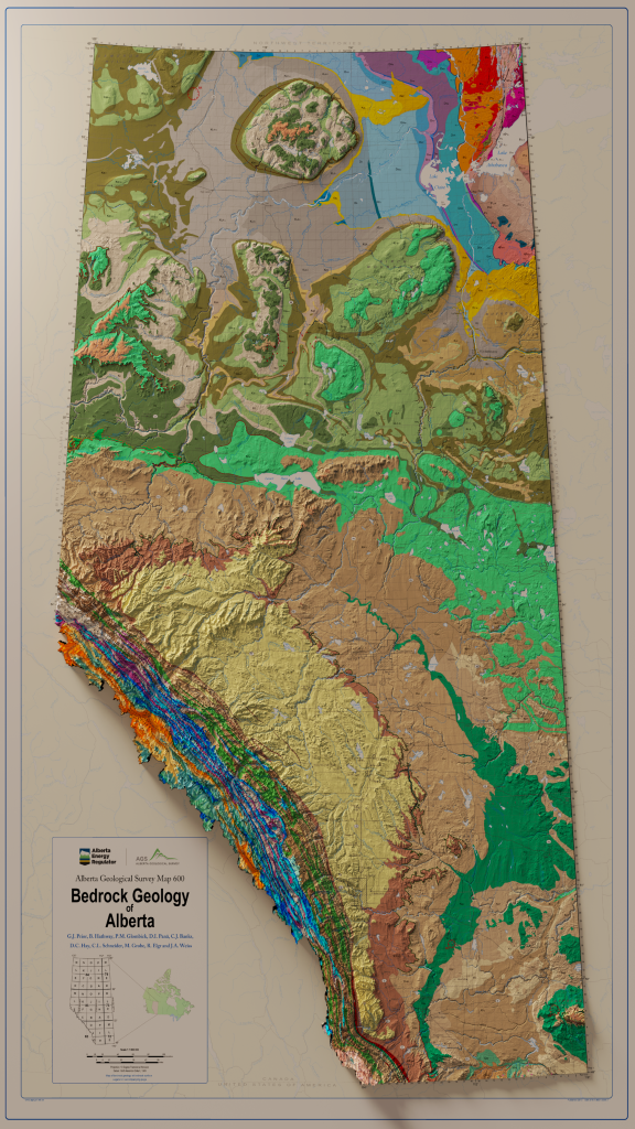
Step 3 View the results
View your results and continue adjusting the lighting to get the look that you want. A great article about lighting to improve relief can be found Here.
Further Reading and Viewing
This article was an overview of how to create a 3D map in Blender using two images. It is by no means a comprehensive, step-by-step guide of the process, so I have added a list of links that have all the information needed to create your own 3D map below.
